Inductive Kickback - The curious case of the fan that didn't
As I was testing and validating the Soldering Smoke Absorber’s electronics, I noticed a curiosity: The input terminals were mostly.. fine?
Here’s a scope capture as the fan’s power was cut (generated from a Rigol DS1102E’s CSV output):
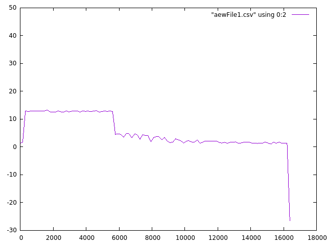 X: time – Y: voltage, GNUPlot settings 1
The ripple at the end is the fan becoming a ‘generator’ as it freewheels to a stop.
Related post: Smoke Absorber Build
Inductive Kickback
One of the more vivid examples of learning electronics involves an electromechanical device (typically a relay) and what happens when it is suddenly turned off.
Cool examples use an LED to show the quick flash of energy that gets dissipated.
Cooler still is the arcing that happens. This is probably around 100v or more from a 12V solenoid:

Inductors
Inductors are essentially a precisely wound coil of wire. They’re a fundamental building block of modern electronics design, having applications ranging from signal filtering to storing energy for switch mode power supplies.
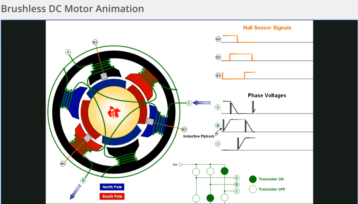
The fan in the smoke absorber build is driven by a brushless DC motor. It switches coils of wire (changing the electromagnetic field) to spin a permanent magnet in a precise sequence.
(It has similar properties to an inductor, in the simplest terms.)
Inductive Kickback
When a power switch is turned ‘off’, its probably normal to assume that that energy just stops flowing.
Faraday’s law of induction2 tells us that inductors have different plans.
The stored energy (in the magnetic field) of the inductor wants to keep flowing after power is removed, but can’t. There’s nowhere to go. But it keeps collapsing into the inductor anyway.
As the magnetic field continues collapsing onto the inductor, the inductor’s voltage rises until it finds (or creates) the path of least resistance.
And at a high enough voltage, air becomes conductive too.
These high voltage arcs damage and destroy components, from switch contacts to transistors. So they’re to be avoided, normally by placing devices called snubbers in their path.
BLDCs (Brushless DC) Fans
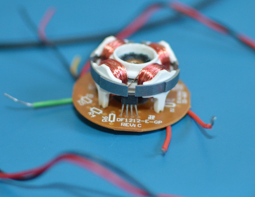
Here is a BLDC fan that has been torn down haphazardly and put back together):
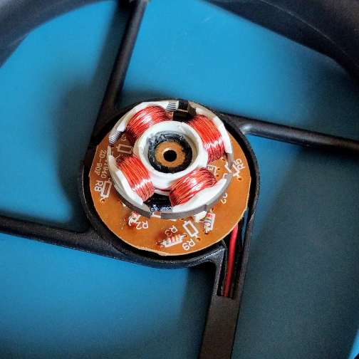
This part with the circuit board and wound wire is the stator (mnemonic: ‘static’).
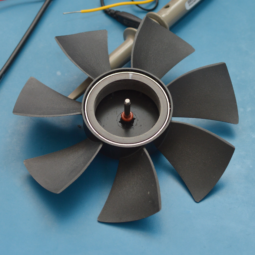
The part with the fins is called the rotor (mnemonic: ‘rotator’) and it has a circular magnet on the inside, which sits around the stator’s coils when the two are slotted together.
When the coils of wire are powered and switched in a precise sequence, the stator makes the rotor ‘chase’ the changing magnetic field, whipping air around via the fan blades.
Driver
See the little black protrusion at the top of the circuit board, in-between the metal fins of the coils?
That’s the BLDC driver and hall effect sensor, which runs the magnetic sequence. The sequence has to switch as the fan moves, otherwise it would stall the rotor.
Knowing that the rotor is moving (with the sensor), the driver can quickly switch the poles to keep things moving.
And if you’re like me, maybe an animation helps? I’m not that great at designing those, but Texas Instruments has a useful animation to commutate this around your brain.
I recommend giving it a look, it’s a really high quality animation!
Show us the kickback
Now that we’ve had a look at the insides, what of the inductive kickback?
Here’s another oscilloscope capture, probing both coils, as a neodymium magnet is being moved across the hall effect sensor.
This switches it from one set of coils to the other and back:
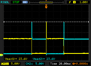
Some sort of inductive kickback is definitely registering (those are the brief spikes on the graph)! At nearly 23V, too. But why doesn’t the kickback happen right away?
I have an idea. Here’s a single scope trace, showing one coil as it is being switched:
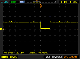
The TI animation shows this, but as a pole reversal (north to south, or south to north) until the inductor is cut off completely – (watch the transistors on the bottom right.
Inductive kickback vs supply
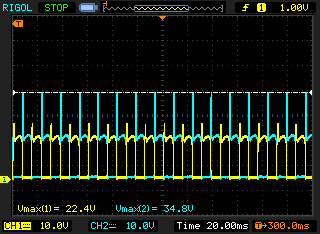
Here’s another capture, showing the inductive kickback and supply:
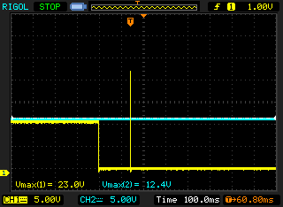
blue trace: 12V rail / yellow trace: inductor
Everything is handled internally.
So where are the diodes?
Like the statement above about snubbers, the standard suggestion that follows is to add a diode in an anti-parallel (striped side points towards +, usually) configuration across an inductive load.
This is preferably a ‘fast’ schottky diode, which starts suppressing/clipping the inductive kickback faster/earlier, before it is able to do harm.
A kickback diode (alternatively named flyback, snubber, freewheeling..) works by circulating the remaining energy through itself and back into the coil, letting the losses in both safely dissipate the remaining energy over time.
But this board has no obviously visible snubbing devices.
Back to the fan
Remember the little IC that had a hall effect sensor in it? Well, it’s a FTCS277 (Feeling Tech) IC3.
The Feeling Tech datasheet [PDF warning] suggests a typical application circuit that looks like this:
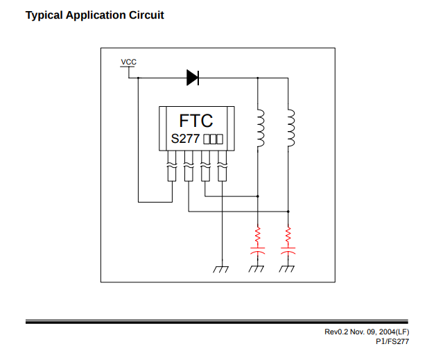
The red highlights alone might indicate that this is a RC (resistor-capacitor) snubber. They’re pretty common 4, but are often placed across (in parallel) a device to be protected (like a switch, or in combination with a diode snubber).
This is not the snubber we are looking for.
Instead, I believe that this is probably an RLC (resistor-inductor-capacitor), and is likely acting as a damper for any high frequency/unwanted emmissions (this particular configuration is also known as a band-pass filter. These occur during the switching of the coils.
(N.B: This fan’s circuit uses 3.3μF capacitors, with a voltage rating of 50V.)
Removing a capacitor
So if there aren’t any visible diodes, are these some kind of weird snubbing capacitors? (It’s unlikely, but hey, lets believe in magic.)
So what happens when a capacitor is removed from the circuit?
Something interesting: The kickback increases for the coil where the capacitor is removed.
It still gets clipped at a fairly precise voltage though. Something else is doing this.
Here’s a block diagram for the FS277. This tells us what is going on inside the chip, and how things are hooked up (from an implementation standpoint).
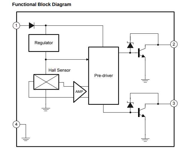
The boxes are hand wavy (regulator, amp, pre-driver..) and don’t tell us much, but the parts at the right are interesting!
Breaking Down
Reverse breakdown is a useful property in zener diodes. Normal diodes tend to be a one way street, but zeners let you safely go the other way, as long as you fit certain parameters (most importantly, voltage).
When a coil is turned off in this circuit, the zener diodes go into reverse breakdown (say, from pin number 2; it flows up and over, toward the “pre-driver”).
It then drives the base of the NPN transistor (that’s the thing with the arrow pointing to the right and down) and opens a path across the transistor for the remaining energy to return.
If the capacitor was still present, it might have smoothed out/clipped the sudden transient a bit, but the zeners still work well enough.
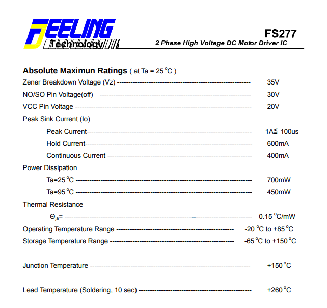
A very specific value
What happens at around 35v though? And why is it that specific value? A look at the IC’s specifications gives the zener’s breakdown voltage at around 35V.
Conclusion
So now we know where the kickback goes: It’s all handled internally by the zeners.
And no kickback diodes are needed across the power input terminals of this case fan (your mileage may vary, check your fan driver’s datasheet, no purchase necessary).
References
GNUPlot settings1:
gnuplot> set datafile separator ","
gnuplot> set xdata time
gnuplot> plot "aewFile1.csv" using 0:2 with linespoints linestyle 1 smooth csplines
2 Faraday’s law of induction describes an inductor’s behavior as it is powered off. It resists any change and will exert a force to oppose it (in this case, the current has stopped flowing, so the inductor opposes it with an increase in voltage until it conducts across air, briefly).
3 Which is similar still to an AH277A.
4 The fan’s PCB does not have that diode at the top of the diagram installed, so you can do fun/horrible things – like starting the commutation by directly powering one coil (it backpowers the IC and hobbles along on one coil).