Buildlog: A soldering smoke absorber
This is a fan that takes a carbon filter cartridge. It’s used to redirect the fumes encountered during electronics soldering.
Research and Prior Work
This is one of many similar implementations. (You probably don’t want to use this one, for reasons stated here.)
For professional/serious use: a commercial unit off of the shelf (like this Hakko unit) is much more appropriate.
It includes a HEPA filter, which is effective at capturing more of the particulate generated during soldering (see: “Measurement of the Performance of Air Cleaners Against the Particulate Element of Rosin-based Solder Flux Fume” – PDF here).
Also: Cheaper, nearly finished units are also available too. These require simple modifications (tape or additional 3d printing) to get you there, but like this unit, are probably best used with external ventilation.
The reason this exists is that I had an extra 140mm fan in a corner.
Where to from here?
If you’re here for the parts and instructions, there is a list in the “Parts” section. Instructions begin right after that.
If you’re intersted in the design process, it’s what follows after this!
Design
I started off in April 2017 by buying a 140mm Noctua fan. It sat in a corner for a while, destined for a quiet dust filter build.
Fast forward to seeing a carbon filter - I threw one in my cart as I was buying robot parts and decided to design a carbon/fan extractor/absorber instead.
With a few changes, I could also use this as a dust filter / air freshener too.
First iteration
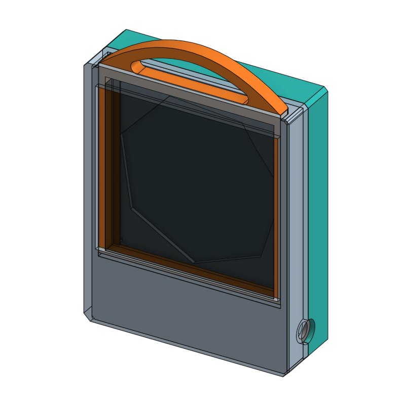
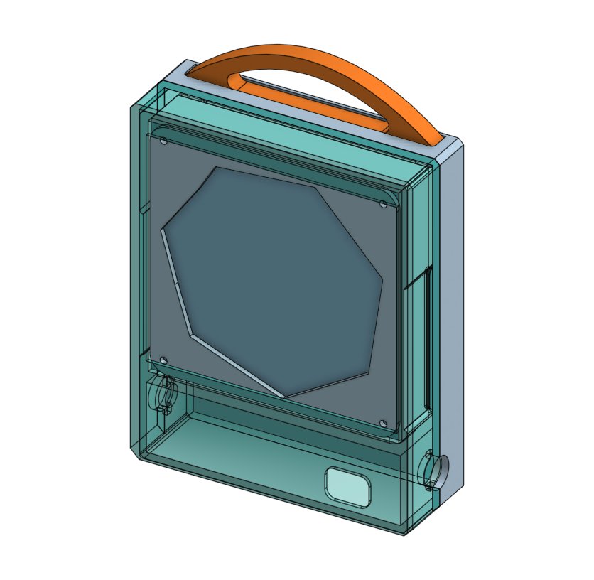
These are from OnShape, a cloud based CAD tool.
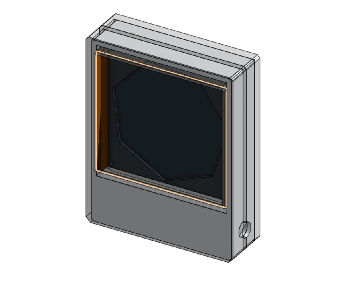
The entire filter assembly, front to back.
Inputting the pieces required extra work up front, but having the flexibility to adjust the spacing between inner-connected components saved a lot of time.
And basic placeholders (the charcoal filter is a squarish translucent black block) helped with rendering speed too.
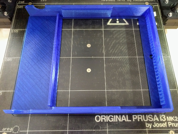
Printing the first version
Each piece here was the size of a large technical book (comparable to a copy of “The Art of Electronics”).
5-8 hours for each piece (there are three), on a Prusa i3 MK2 with a 0.2mm height setting and normal speeds.
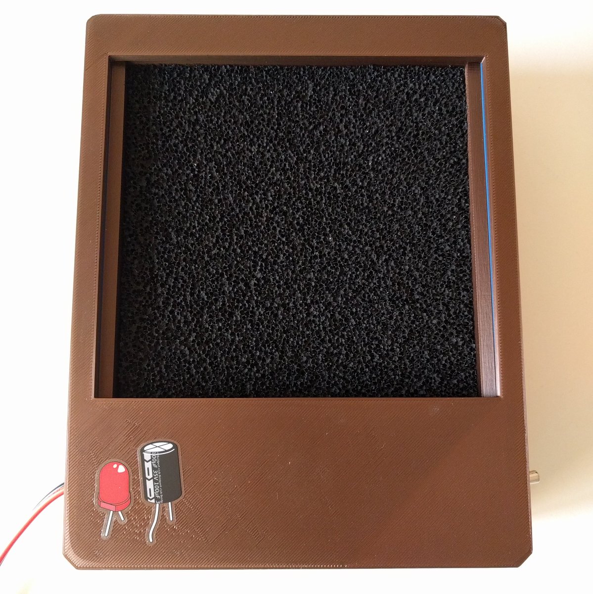
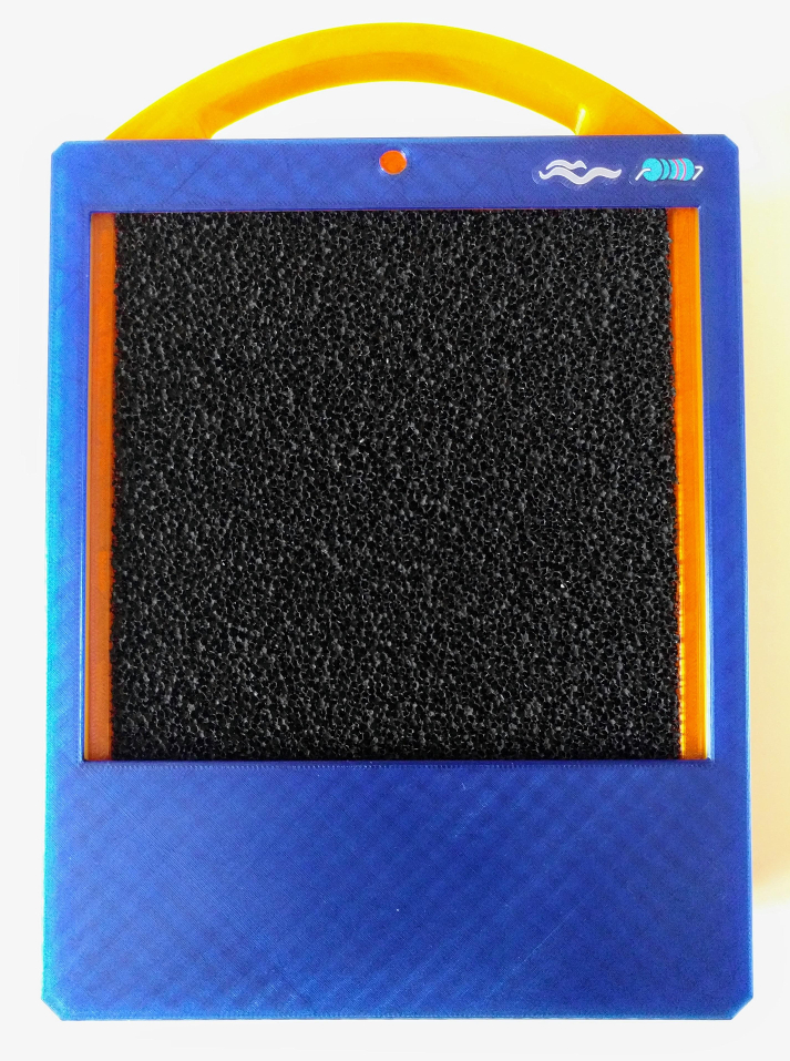
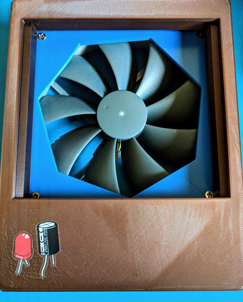
The carbon filter, nestled in the case nicely.
(The stickers are from Boldport’s sticker CAD sheet, bringing more attention to an uneven spot in the bed)
The fan and fan spacer (with the filter removed). This kept the fan blades from chipping away at the carbon filter and served to keep both a set distance apart.
The cutout on the back cover is unused in the final version, but here, it was designated for a rocker switch/speed control/add-on.
There were several errors in this version:
The front cover’s tolerances were tight enough that it required hammering in with a rubber mallet.
Conversely, the rear cover ended up being too loose, with 0.2mm of spacing in all directions.
The toggle switch on the side (it is the metal protrusion, bottom left) pushed the casing apart. The hole was correctly sized for the switch to come through, but the retainer’s overall diameter pushed on the cover pieces slightly.
The filter itself was hard to remove. It required digging in with a tool or displacing the fan from the rear and knocking the filter out.
Improving on the first version
User-friendliness of the filter became a priority in the updated version.
This added a cartridge system. The fan could be used for other things with or without the filter. Great for really warm days, drying boards off and keeping the carbon element fresh in-between uses.
The holes on the sides were resized, to allow for the toggle switch’s retainer to fit. One side was also resized to fit a panel mount DC jack.
These holes also had external cuts added, allowing them to accept smaller sized mounts (with an adapter).
Tolerances were revisited and the rear panel was made to take an additional spacer.
Cartridge handle
Before I could print all of the second version, I figured that the cartridge handle could double as a handle too, but it needed a bit more security.
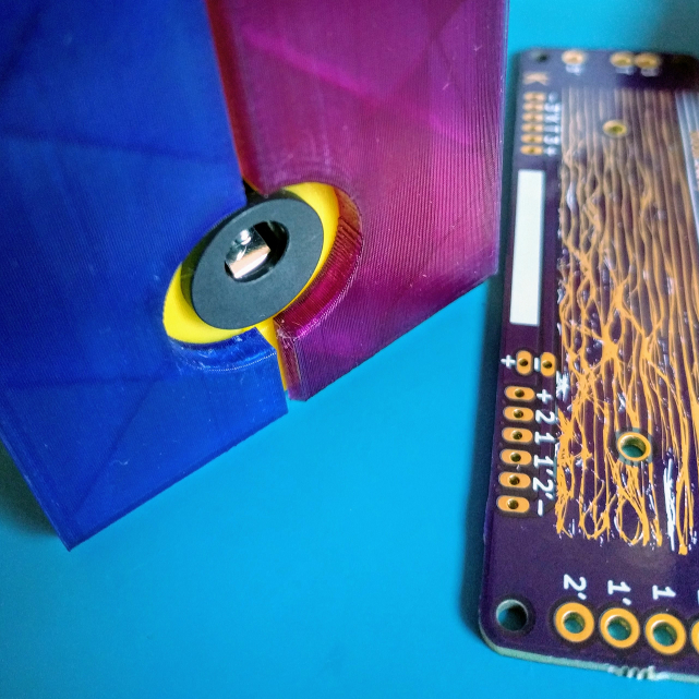
The cartridge was made to take an M3 screw (currently setup for tapping, but can also be changed/resized for a heat-set brass insert using the STEP files).
The cartridge is now loose fitting, so it can’t be mistaken for a secure handle (the screw needs to be inserted, maybe a pop-up eject button next?).
There are new slots and protrusions in the cover pieces and case. These lock the cover pieces together vertically but still allow relatively easy separation, horizontally.
With the screw in place, the cartridge’s handle acts as a carrying handle for the entire unit.
Version 3: Printed
It still looks pretty boring in CAD! I think this is a good thing.
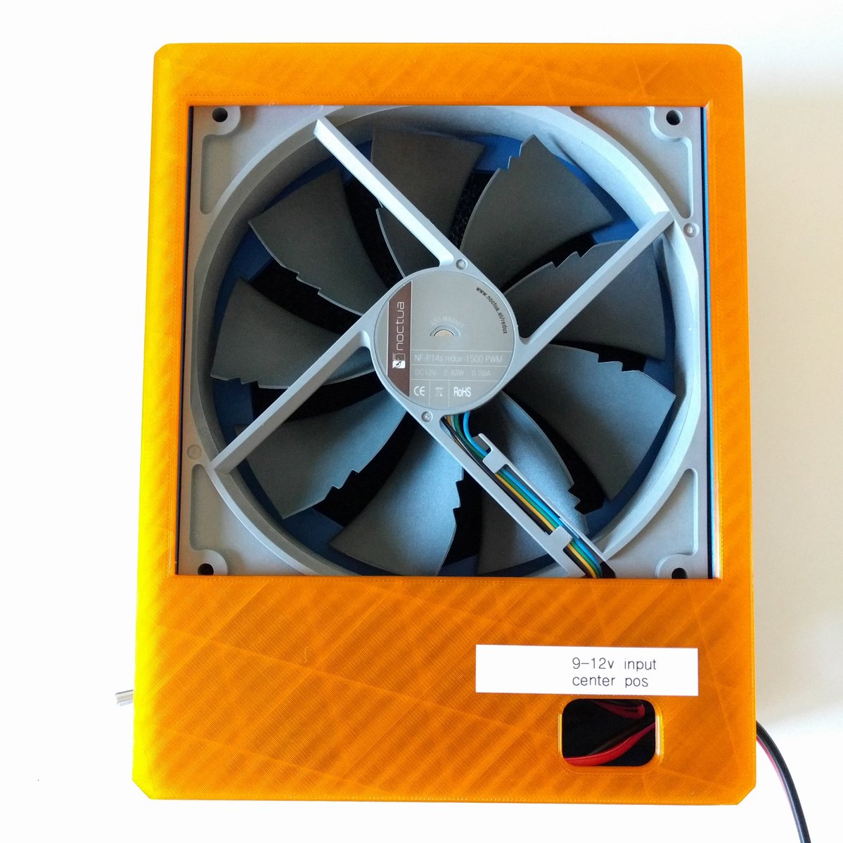
Here’s the outside where the panel mount DC jack is. Some deburring was needed here before the jack would seat properly.
Sandpaper would work just as well if you encounter this issue too.
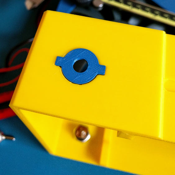
This is the toggle switch’s plate. It allows for different sizings of switches to be inserted. The press-fit is fairly tight.
The cartridge slides out smoothly too.
Future considerations
A better version of the cartridge might be a printed quick snap/eject button of some kind
The case’s fan to cartridge separator (the top lip) could be a bit more aggressive (limited by support/overhangs). The fan can fall past the lip and obstruct cartridge insertion sometimes.
Parts of the cover/case might be better designed as modular snap in panels, so that different configurations of switches / controllers / add-ons could be used without reprinting everything. It might also make the case/cover faster to print.
A HEPA filter
PWM speed control: for very loud fans, or people who don’t want 100% speed all the time.
Moving power and the switch to the same side (so that the fan can be used on its side)
Adding a tiling system so that surfaces can be cooled
Parts
Here’s the part list! If you’re doing this on your own, please substitute or add as you wish. It’ll hopefully end up being your number one fan.
Tools
Soldering iron with solder (crimped connections would be better but crimp connectors and crimpers are a rabbit hole and require practice to get right)
Wire strippers
3D printer with a bed size that can accommodate this print (the i3 MK2’s is 250 x 210 x 200 mm); lengthy side of the large pieces: 201 mm, wide side: 160 mm)
Materials
Amazon
A Noctua 140mm fan - I selected this Noctua based on a combination of performance/silence, with cost being a more minor factor. If cost were no object, I’d move up to this industrial grade 140mm Noctua instead. However, I don’t think it is that great of a step up.
Carbon filter (5-pack), if you want it in ones, look below: https://www.amazon.com/gp/product/B079D5W2C2/
Adafruit
2.1mm panel mount jack: https://www.adafruit.com/product/610 (test desired pins by plugging in power and carefully verify with a voltmeter before soldering – the assembly images might help too).
SPDT (Single Pole, Double Throw) toggle switch: https://www.adafruit.com/product/3221
2.1mm center-positive 12V DC switching power supply: https://www.adafruit.com/product/798
Carbon filter: https://www.adafruit.com/product/3836
Heatshrink tubing: https://www.adafruit.com/product/1649
Optional/missing/no proper source
- Wago connectors: I keep a box of Wago connectors around; they’re really nice for an easy, solid connection.
Adafruit sells a 3-conductor version with a window. I’ve been using a box of the gray two-conductor connectors off of Amazon, so I’ve not needed to use the newer versions.
- Fan cable: A cable that converts the four pin header to two wires makes things more elegant (chop off the wiring on the large end and put each into the wago connectors).
Something like this – I wouldn’t recommend going out to buy one though! Soldering silicone wire to one end of a 2.54mm header will work in a pinch (use hot glue to keep it attached to the fan header).
- M3 tap: For tapping a hole into the cartridge.
3D prints
The prints are in this repository: https://github.com/Collector3/fume-away (now on YouMagine and Thingiverse as well, if you came from there, hello!).
Print the cartridge, case (enable support material), cover (enable support material), rear-cover, rear-fan-grill, and fan-grill files.
If you’re using the smaller SPST switch, print the 6mm adapter as well.
Assembly Instructions
The prints take a long time, but assembly is (hopefully) straightforward.
Fan
Screw the fan-grill and rear-fan-grill pieces onto the fan, using fan screws (four are included in the Noctua box, use two in a diagonal configuration for each). They should tap into the plastic and into the fan itself (try to drive them straight in).
Carbon Filter Cartridge
Tap the hole if you want to use the cartridge as a carrying handle with an M3 tap. Choose any screw size that keeps the cartridge in place and engages the front cover. An M3 x 16mm was used in development.
Toggle Switch
With a multimeter in continuity mode (aka beep mode), check the switch to see which contacts you’ll be wiring to. Power input goes to the center pin and it is distributed to the two ‘poles’ on either side, as the switch is flipped.
Counter-intuitively, the ‘on’ position means the bottom tab is connected to the center pin (just ‘flip’ the switch around physically if soldered backwards: nobody will know).
Strip two wires, red/red, cut & add heatshrink tubing, then carefully solder the wires to the switch. Use a blow dryer or quick flick of a lighter to tighten the heatshrink.
Toggle Switch
To attach the toggle switch, tap the 6mm press-fit mount into the case, like this:
It should fit snugly; if it doesn’t, a bit of glue/epoxy will help to keep it in place.
To attach the switch, unscrew the top retainer and the ‘external lock washer’ (looks like a spiky dog collar, feels prickly) from the toggle switch.
Insert the toggle lever from inside the case and push it through to the outside. Then screw the retainer and washer onto the top to secure it.
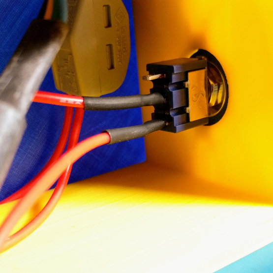
DC Jack
With this jack, the negative poles will switch connectivity depending on whether or not a DC jack is inserted.
To absolutely verify which pins to solder to, use a multimeter and carefully measure the voltage across the pins, with the power supply plugged in. It should read 12V and indicate which pins are positive and negative (if you get a -12V reading, the multimeter’s leads are backwards).
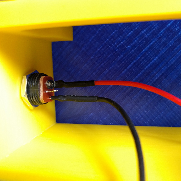
Strip two wires, red/black, cut & add heatshrink tubing, then solder the wires to the panel-mount jack. Again, use a blow dryer or lighter to tighten the heatshrink.
Note: If at first, the panel mount jack does not fit, use a bit of sandpaper or a deburring tool to widen the hole, as different printer-to-printer tolerances can deposit a little more in this area.
Attach the panel mount jack to the case from the outside, pushing in (threading the wires in first). Secure it to the case with the retainer from the inside.
Final wiring
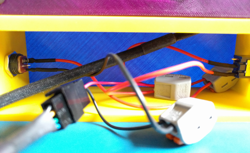
If that picture looks confusing, it is! We’ll break it down together.
Text version
We’ll start by following the conventional path of current flow. From the power supply brick, it goes into the positive pin of the DC jack. Then it enters a wago connector and exits to the center pin of the toggle switch.
From the center pin of the toggle switch, it exits to the bottom pin (when in the on position), into another wago connector.
Another wire from the connector then connects to the positive pin of the fan’s yellow wire.
On the negative side, the fan is connected to one wago connector, which is then connected to the negative pole of the DC jack.
How about a diagram?
You got it.
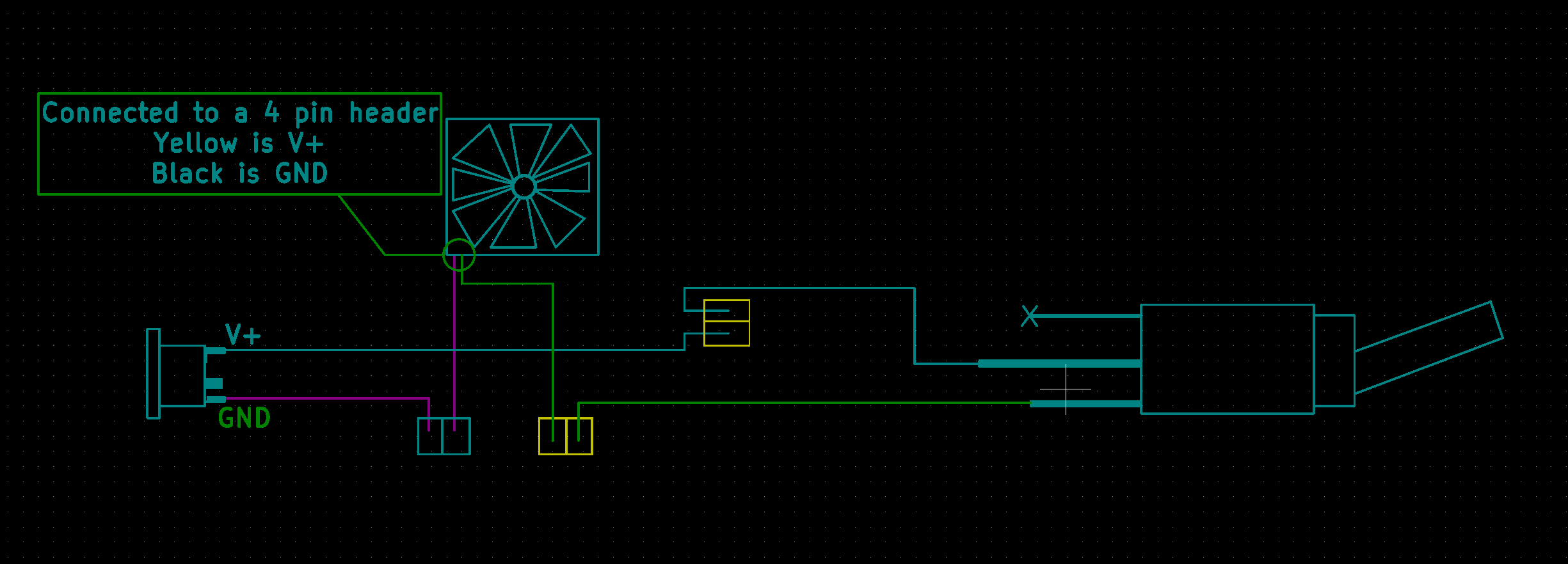
Also: If you’re super confident that nothing will be re-used, and that there are no further improvements to be made, feel free to do away with the wago nuts and wire/solder/crimp directly.
Case assembly
Push the carbon filter into the cartridge.
Attach the front cover to the case.
Route the fan’s cable into the case. It may need to be wrapped around inside the case a few times.
Push the fan into the front cover from the back of the case. Have the label facing you (so it sucks in air through the filter).
Connect the fan to the power connections we routed above.
Fan connection
If you’ve acquired a four pin to two pin molex fan connector, now would be the time to substitute it in.
Other options include using a 2.54mm Male/Male header as a go-between (soldering wire to one end) and hot gluing everything so it stays in place.
Cutting the fan header off and attaching the yellow (positive) / black (negative) ends to the switch/DC jack would also work in a pinch.
Final case assembly (continued)
- Push the rear cover over the case. Attach DC power and flip the switch. If everything is wired correctly, the fan should begin to immediately spin up.
If it doesn’t, pull out the power brick and check your wiring. With the fan cable disconnected, connect the power brick and probe around with a multimeter. You should see 12v with the switch in the ‘on’ position.
Conclusion
This about completes the build process. If you’ve made it this far, thanks!
It’s rather unlikely that there will continue to be updates to this build (i’ll probably revisit it to add a HEPA filter if my soldering area changes), but if you are interested in improving it for your own uses, please grab the STEP files and make this build your own.
Until next time.