AVR Programming with Adafruit's Atmega32u4
Introduction
This guide will help you build your own LUFA AVRISP-MKII clone using the Adafruit Atmega32u4 breakout board.
Build Materials
Linux
You will need Linux as a base for programming and compiling the LUFA project’s code. Using another operating system is possible, but won’t be covered here (sorry!) If you don’t have a dedicated Linux installation, try a Linux live CD and install the packages below to program.
Installation of AVR tools are provided for the Ubuntu and Fedora Linux distributions.
Adafruit Atmega32u4 breakout
A modified LUFA CDC bootloader comes pre-installed on these. This allows the chip to be programmed without an external programmer (at the cost of some memory space).
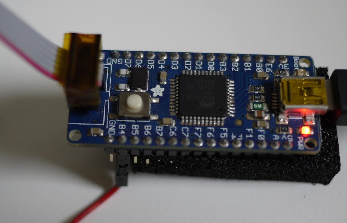
For programming breakout boards, a 6-pin cable is attached to the programmer. A wire is hooked up to B4 (which connects to the target AVR’s RESET pin).
Note that without modification, the RESET line will trigger on the 6-pin cable as a part of the programming process through B4. Since the 6-pin cable connects RESET between both target and programmer, the programmer itself will reset when B4 is asserted (which ends the attempt). This gets worked around a little bit later by splicing into the wire.
This method is mostly optional, but useful since some breakouts are only programmed easily through the header.
Breadboard, wires, and maybe a ZIF socket
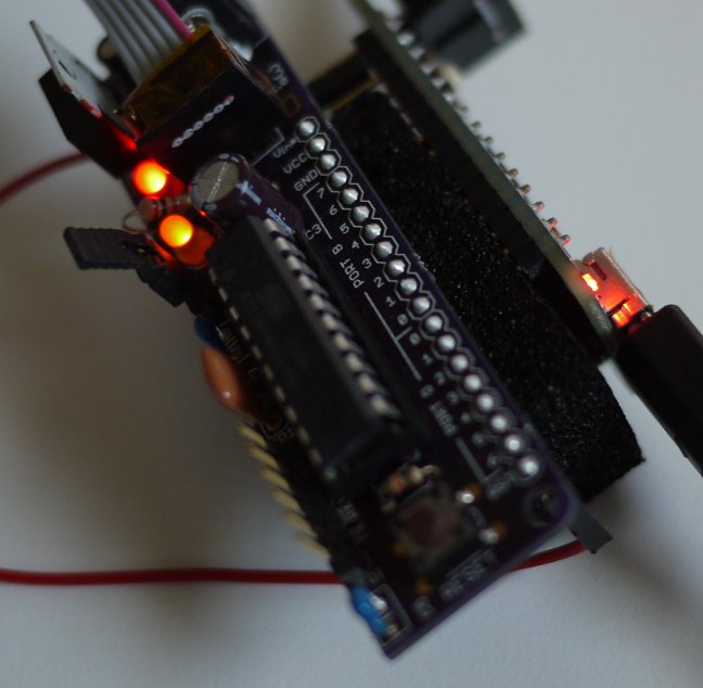
It is also possible to use a breadboard to program a chip. A completed layout looks something like this.
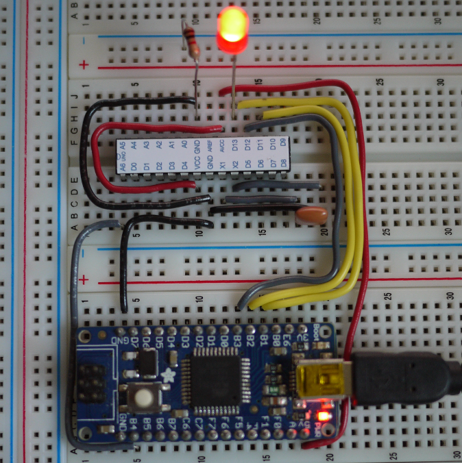
There are problems with this setup:
Removing the programmed chip may be difficult/annoying. A ZIF (zero insertion force) socket may be appropriate if programming a large quantity of chips.
Depending on fuse settings, the recovery clock (or, as seen in the picture, a resonator) may be needed in order to program the chip properly. Breakout boards usually have some sort of clock source installed.
For most, it may be better to program using a dedicated PCB that has the 6-pin header broken out. This might be an Arduino for Atmega328Ps, or the BB313 for ATTiny chips.
Here are the necessary connections from the Atmega32u4 breakout to the chip being programmed (if using a breadboard):
Connections for breadboard
32u4 -to-> Target chip
B1   ----> SCK    (Arduino Digital Pin: 13)
B3   ----> MISO   (Arduino Digital Pin: 12)
B2   ----> MOSI   (Arduino Digital Pin: 11)
B4   ----> RESET  (Arduino Analog  Pin: A6)

GND  ----> GND    (Note: 1)
VCC  ----> VCC    (Note: 1)

Recovery Clock    (Note: 2)
B5   ----> XTAL1  (not needed for Arduino boards)


1. There may be extra tie in points for these.
   Check the datasheet to be sure.
2. The recovery clock can be used if your fuses are set incorrectly.

   If using the recovery clock, be sure to set the programing speed to 125KHz
   1/125000Hz = 8x10^-6 seconds (or 8 microseconds, since 1 microsecond -> 1x10^-6 seconds)
   For avrdude add this as a parameter to set the microsecond bitclock period:
            -B 8
- Optional (for a more compact setup): 6-pin IDC cable
A 6-pin cable will stop the programmer from becoming a bundled mess of wires. This works since most of the necessary pins (MISO/SCK/VCC/MOSI/GND) are broken out to the header. However, since both RESET lines are connected, the programmer itself will be reset if connected without modification.
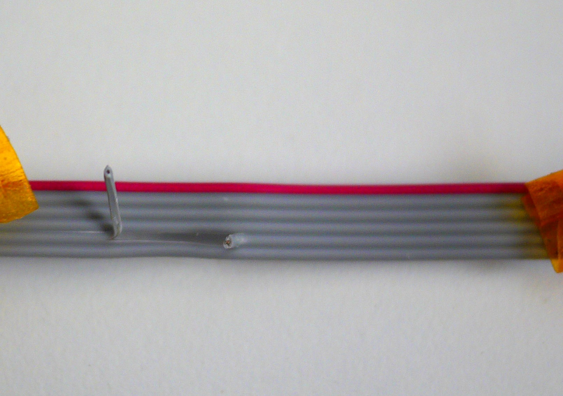
Here is an example of the 6-pin cable which has been cut with a sharp knife. The line to cut is the 5th wire, starting from the red line as shown in the picture. If you aren’t sure, verify with a multimeter that the line is indeed the one used for RESET.
To verify: With your spare Arduino or other breakout board, just plug a wire into the RESET line (connected to a lead on your multimeter in continuity test mode – aka ‘beep beep beep’ mode), and connect the 6-pin header (red stripe to small dot, or box connector “tab” to the proper place). Poke the small wires coming out of the box to check. You may need to press with a bit of force.
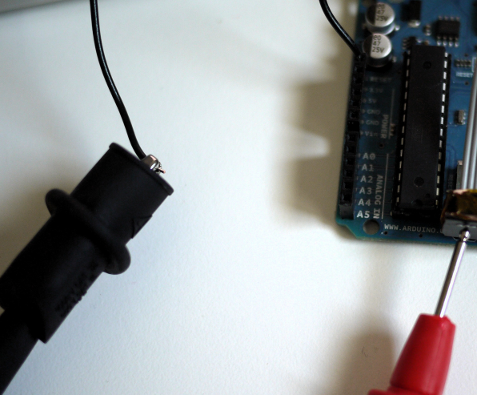
For the absolutely paranoid, pulling apart the box connector may be a good idea.
Other ways around cutting up your cable: fuse manipulation, designing your own PCB (as some have), cutting header pins, etc. If you end up using this particular method, soldering up a detachable wire to the cable’s RESET (then connecting to the programmer’s B4 pin) might be a worthwhile project.
- Female/Female jumper wire(s) (Female/Male, Male/Male, etc)
A wire to connect the reset line (B4) and other pins. You might need a single piece of male header to tie the jumper wire to your destination board. The RESET line is triggered using this connection.
Finding your board
Linux
I’m using Linux, so when I plug in the board this shows up after typing dmesg into a terminal:
[15138.776119] usb 3-1: new full-speed USB device number 51 using xhci_hcd
[15138.791800] usb 3-1: New USB device found, idVendor=239a, idProduct=0001
[15138.791806] usb 3-1: New USB device strings: Mfr=0, Product=1, SerialNumber=0
[15138.791808] usb 3-1: Product: AVR CDC Bootloader
[15138.793350] cdc_acm 3-1:1.0: ttyACM0: USB ACM device
ttyACM0: USB ACM device on the last line is where data gets accepted. There are a myriad of other ways to figure that out,
but parsing dmesg will tell us if it failed to enumerate somehow.
Download LUFA (Linux)
The next step from here is to download the files necessary to load the programmer. Run the following (after acquiring git [1]).
$ git clone https://github.com/davidk/lufa.git
Cloning into 'lufa'...
remote: Counting objects: 52669, done.
remote: Compressing objects: 100% (10637/10637), done.
remote: Total 52669 (delta 42901), reused 51050 (delta 41412)
Receiving objects: 100% (52669/52669), 9.49 MiB | 497 KiB/s, done.
Resolving deltas: 100% (42901/42901), done.
This is a small fork of Dean Camera’s LUFA project (a framework for developing USB-enabled AVRs). Of interest is Dean’s clean-room copy of the AVRISP-MKII programmer, which turns the Atmega32u4 breakout into a programmer for other AVRs (egg, meet chicken). Run the following from outside the lufa directory.
$ cd lufa/Projects/AVRISP-MKII/
$ git checkout atmega32u4-avrisp
  Branch atmega32u4-avrisp set up to track remote branch
  atmega32u4-avrisp from origin.
  Switched to a new branch 'atmega32u4-avrisp'
Once you’re in the branch, ensure that your avr utilities are installed.
For Fedora users:
$ sudo yum install avr-binutils avr-gcc avr-libc avrdude
Ubuntu users:
$ sudo aptitude install gcc-avr avr-libc avrdude
Programming (check to see if your boot light is fading in and out, if not, press the white button and run the following):
$ sudo make avrdude AVRDUDE_PROGRAMMER=avr109 AVRDUDE_PORT=/dev/ttyACM0
Connect the programmer
If it all went well, you now have a programmer.
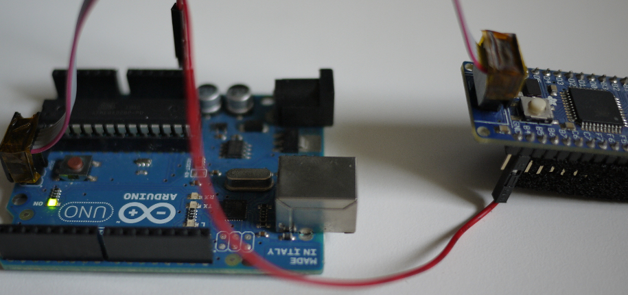
Remember: The single red wire goes from B4 to the Arduino’s RESET pin.
Start your engines
At this point, all the hard work is done! Before programming, make sure that the RESET line is connected to B4.
avrdude can be used to program a board by running it as such:
# For Atmega328P chips
$ sudo avrdude -patmega328p -cavrispmkii -Pusb -Uflash:w:Blink.cpp.hex

# For an Attiny4313
$ sudo avrdude -pattiny4313 -cavrispmkii -Pusb -Uflash:w:blinky.hex
An example session (targeting an Attiny4313 with the blink program from the bb313 website):
$ sudo avrdude -pattiny4313 -cavrispmkii -Pusb -Uflash:w:blinky.hex
[sudo] password for davidk: hunter2

avrdude: AVR device initialized and ready to accept instructions

Reading | ################################################## | 100% 0.00s

avrdude: Device signature = 0x1e920d
avrdude: NOTE: FLASH memory has been specified, an erase cycle will be performed
 To disable this feature, specify the -D option.
avrdude: erasing chip
avrdude: reading input file "blinky.hex"
avrdude: input file blinky.hex auto detected as Intel Hex
avrdude: writing flash (60 bytes):

Writing | ################################################## | 100% 0.02s

avrdude: 60 bytes of flash written
avrdude: verifying flash memory against blinky.hex:
avrdude: load data flash data from input file blinky.hex:
avrdude: input file blinky.hex auto detected as Intel Hex
avrdude: input file blinky.hex contains 60 bytes
avrdude: reading on-chip flash data:

Reading | ################################################## | 100% 0.02s

avrdude: verifying ...
avrdude: 60 bytes of flash verified

avrdude: safemode: Fuses OK

avrdude done.  Thank you.
Programming without using ‘sudo’ or root (Linux)
Running avrdude as root is kind of excessive, even temporarily. To run it as a normal user, we can eck out the following to make it work properly:
First run groups to get the list of groups your user currently belongs to:
$ groups
davidk dialout wheel
This determines what we set in the GROUP=“” field below (in this case i’ve picked wheel):
$ sudo su
# echo 'ATTR{idVendor}=="03eb", ATTR{idProduct}=="2104", GROUP="wheel", MODE="0666"'
>> /etc/udev/rules.d/60-avrispmkii.rules
# udevadm trigger
Thanks
Special thanks to Dean Camera, who saw that I was making changes to my fork on Github (which is a mirror of his SVN repo) and stopped by my lowly branch to suggest a small change. Good guy (he did it again too, on an unrelated branch).
Problem?
Tack on something here. I will try to help or spin you in the right direction.
Reference(s)
[1] Get git via your preferred package manager, or check out http://git-scm.com.
Updates
01-15-13: Added information on using avrdude in a non-root fashion for Linux. Also threw in some magic to make console stuff pretty.