(5/11/13) - Hey fantastic reader: This is an old how-to (from 4/2/12!) that existed in its own self-contained repository. Reflecting back, this hack was kind of silly, but i’m porting it here to keep everything in one place.
And if you’re curious about the long-term viability of this build.. it is still kicking. The detents are a little less crisp now, but everything works a treat. (And now, back to your regularly scheduled post re-run!)
It wasn’t too long ago that volume control on a keyboard was a foreign concept. After it became a ‘feature’, that control seemed pretty normal. There is however, a slight modern exception now. Many mechanical keyboards (which have been coming back into style) don’t have them.
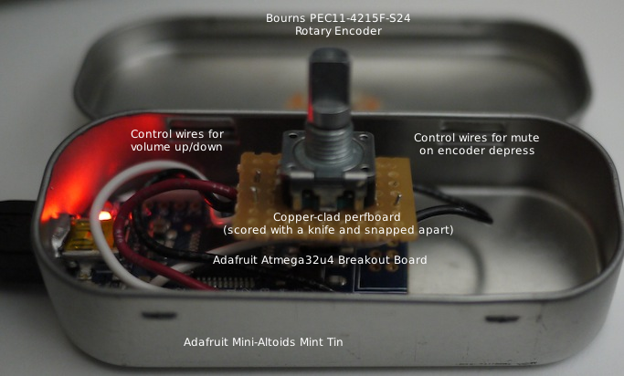
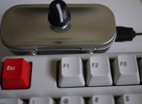
In response, I hacked this together. It’s a volume controller which parses a rotary encoder’s input and controls the volume (tested on OS X/Windows/Linux so far).
Parts/Bill of Materials:
Altoids Gum sized tin - A slick enclosure. Scratches easily though.
Rotary Encoder - I’ve tried a bunch. A lot of them either failed over time, or the ‘clicks’ (detents) became mushy. This one comes with a cool looking knob and is panel mountable too.
Adafruit Atmega32u4 Breakout - Brains of the operation. Comes with headers. For this particular project, just keep the headers for a rainy day.
Wire - Will need these to hook up the rotary encoder. Stranded wire is preferable since it can bend and flex.
Perfboard - While you can go without, the perfboard is nice to relieve the stress on the rotary encoder pins. I haven’t run across an economical source of cuttable copper-clad perf; they’re usually so large that I feel guilty slicing them apart. These seem to be the right size, but are rather thick (I haven’t sliced these apart yet). Use anything that works.
Optional (or you already have these if you’re thinking this is a good weekend project):
Sugru - I used this stuff to attach the board to the tin. Anything non-conductive works (determine the amount of adhesion based on your projected re-use of these parts).
Soldering iron + Solder - Needed to join all the parts together.
Mini-B USB cable - This is the cable type that the breakout board accepts.
Drill/set of bits - To make a hole so that the encoder can poke out of.
Something to cut with - For perfboard cutting, wire stripping, prying the enclosure, etc.
Electronics assembly
Start by cutting perf for the rotary encoder. Put on your safety glasses (and quite possibly a dust mask just to be extra cautious). Cutting perfboard (and other things too!) can cause pieces of it to fly into your eyeballs.
To cut the perfboard by hand, score 5-7 times along the holes that mark the edges of the cut (make sure to dry fit before cutting). I had better cuts by scoring along the entire length of the perf (although this means some perf ends up being wasted).
Once you’re ready to cut, take a pair of shears (dull diagonal cutters work too) and clip a notch where your scored lines meet the edges. This should serve as a guide for your snap (the concept is similar to tearing a notch in a piece of folded paper before ripping it apart cleanly). Slowly bend the perf where the score is and the perf should snap apart. If it resists or seems like it won’t snap along the score line, score some more and repeat.
If that fails, break out a dust mask, a pair of safety glasses (you should already be wearing these!), and just start hacksawing. It won’t be very pretty, but it should work.
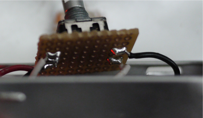
The next step is to solder the encoder in. Insert the encoder and tack a leg with solder to hold it in place. Ensure everything is aligned the way you like it (check that there is room for the wiring below), and solder the rest of the pins in.
The wiring can be deceptively tricky. Measure out enough wire so that you can open/close the box. Cut, strip and tin the wires. You’ll need 5 wires.
Here is the wire mapping (looking from top to down at the rotary encoder, with three pins on top and two on the bottom):
Volume Up/Down (three pins, top)
| Wire color | Pin on Atmega32u4 | Pin on encoder |
|---|---|---|
| White | D0 | Left-most pin |
| Black | GND | Middle pin |
| Red | D1 | Right-most pin |
Mute On/Off (two pins, bottom)
| Wire color | Pin on Atmega32u4 | Pin on encoder |
|---|---|---|
| Black | GND | Left-most pin |
| White | B0 | Right-most pin |
Solder all the wires together. Once the wires are attached to the perf, blob some solder to bridge the wiring and the encoder pins together.
Enclosure
To drill a hole for the encoder, find a bit size that matches (the datasheet says it is 6mm / .236 inches or just around a 15⁄64 drill bit (.234 inches)). Measure for dead center on both axes (or like a professor once told me: ‘eyeball it until your OCD stops’). Mark the drill point.
If it makes it easier, it is possible to remove the lid from the body. Simply bend the hinged tabs outward and the lid will slide off. Reverse to fit the lid back on.
You may need to brace the back of the drill area with a block of scrap wood to prevent warping. Drill from the outside in (so that all the unsightly edges are hidden somewhat). Don’t apply too much pressure (you won’t be able to undent things easily).
Once you’re done, dry fit the encoder but don’t screw it into place yet.
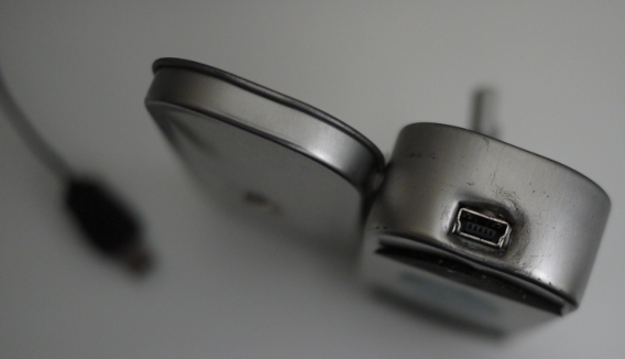
For the USB port, buttress the breakout board against the bottom of the enclosure and mark an approximate outline. Using a drill, begin drilling into the case (the hole won’t be large enough, but we’ll fix that in a bit). With the hole made, take your shears and carefully pry to make an opening wide enough for the USB plug to poke out. Continue to check the fit while slowly prying. Don’t worry if it looks too ugly. The USB plug covers up most of the mess.
Final assembly
Before adhering the breakout board (permanently, depending on your preference); lets test everything.
Compiling:
Unfortunately I haven’t had all that much luck compiling on OS X (using Homebrew packages), and I haven’t tried on Windows at all. Only Linux has worked so far. All hope is not lost however, you can manually program the breakout with avrdude! Read on to ‘Skipping all of that’.
These are the packages I have installed for Fedora which are needed to compile:
$ sudo yum -y install avr-libc avrdude avr-gcc avr-binutils git
Next, grab a copy of the LUFA git repository that includes the necessary modifications:
$ git clone git://github.com/davidk/lufa-lib.git
$ cd lufa-lib
$ git checkout -b atmega32u4-mediacontroller origin/atmega32u4-mediacontroller
$ cd trunk/Projects/MediaController
$ make all
If the compile was successful, connect the breakout board to your computer. Type the following into your console, hit enter, but don’t type in your password yet.
$ sudo make program
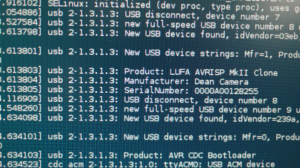
Going back to the breakout board, hit the white button (a green light should slowly start fading in and out indicating that the breakout is ready to be programmed). Type in your password and watch it go. If avrdude had
problems finding your 32u4 breakout, run dmesg and check the output for something along the lines of ttyACM. The last part should be a number. Modify the makefile with the new port and re-run the line.
Here is what my dmesg looks like:
Skipping all of that:
If you’re on OS X or Windows.. or just don’t like compiling, get the hex file, press the white bootloader button, and run the following (a working example for OS X):
$ avrdude -p atmega32u4 -P /dev/tty.usbmodem621 -c avr109 -U flash:w:MediaController.hex
Change /dev/tty.usbmodem621 as appropriate for your platform. On OS X, if at first /dev/tty.usbmodem612 doesn’t work, use tab-completion to fill in the remaining section. Enter /dev/tty.usb and tap tab to get relevant entries when the bootloader light is active.
Finishing up:
Do volume up/down and mute (pushing down on the encoder) work properly? If so, time to finish up! If not, make sure
that the board is programmed (it shows up as LUFA Media Controller in dmesg, and similarly under the OS X System Profiler). Also ensure the connections between all the parts are nice and solid.
If everything is finished, open a pack of Sugru (or the adhesive you’re using), and stick things together. Next, poke the rotary encoder through the hole on the lid. Then secure it with the hardware provided and add the nice looking control knob to top it off.
Here is what mine looks like now; it is magnetically attached to the keyboard (no ill effects yet).
Attributions:
This project uses code and examples provided by LUFA (which is MIT licensed). Thats by Dean Camera. The code to read the rotary code comes from a posting by circuitsathome here.
Improvements, chaos, and cost reductions:
From a performance and cost perspective, the breakout used for this project is overkill; building an ATTiny breakout might be more worthwhile. Also, it might be possible to just rip the guts out of an old keyboard and use its media controller functions with some modding.